
First Person View (FPV) System
This blog describes a 5.8 GHz analog FM long-range FPV system capable of up to 1.5 miles of range. The airborne components of the system are shown in the picture below, consisting of the 5.8 GHz transmitter and antenna, a single-axis stabilized Hyperion gimbal, and 1200 TVL video camera. The Ground Station (not pictured) consists of a tablet, tripod and Eachine 150 CH Diversity Receiver. These can be viewed through the links provided in the Bill-of-Materials also below. The UAV pictured here is the Robotics-In-Flight PiQuadTM.
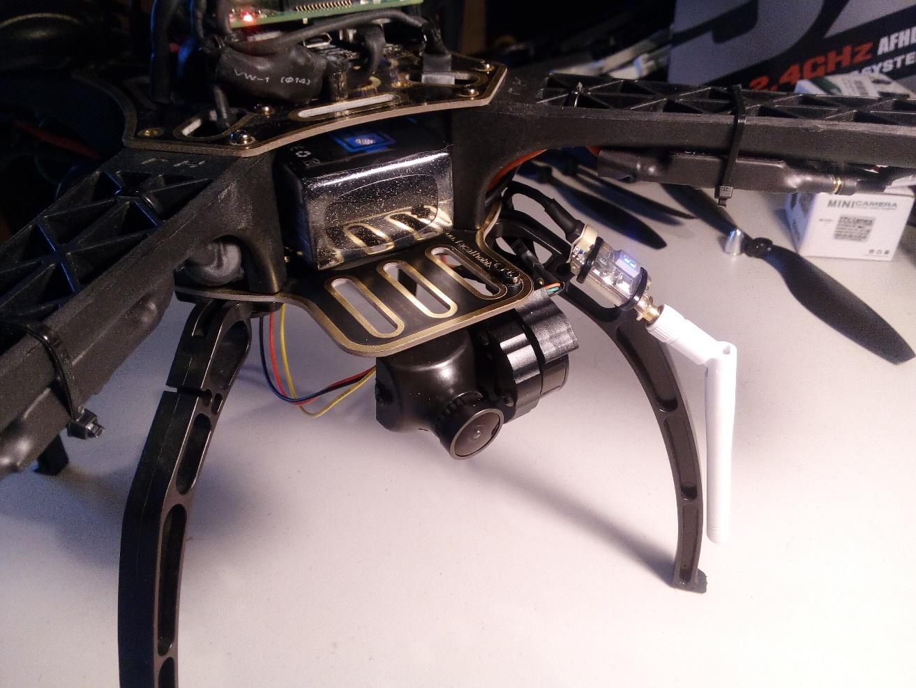
Figure 1 – Picture of Airborne Segment attached to a typical drone UAV
The Bill of Materials
| Name | Unit Cost | Manufacturer | Vendor | Link |
| Ground Station | ||||
| FPV Video Rx for Android Tablet, 5.8GHx 150ch (ROTG02 UVC OTG) | $38.00 | Eachine | Walmart | link |
| Tripod, and Samsung Tablet Mounting Bracket | $20.48 | Ebay | link | |
| Samsung Galaxy Tab A 8.0″ 32 GB Wifi Android 9.0 Pie Tablet Black | $76.00 | Samsung | Amazon | link |
| Airborne Node (stabilized, 1-axis) | ||||
| Hyperion Vengance 2-axis gimbals and camera | $15.00 | Hyperion | Hyperion | link |
| FPV Video Tx 5.8GHz, 800mW, Long Range Tx805 | $22.45 | Eachine | Ebay | link |
| 1200TVL CMOS Mini FPV Camera– Alternate camera | $24.00 | Foxeer | Banggood | link |
| Total –> | $195.93 |
Assembly
This section describes the process for installing the 5.8GHz First Person View (FPV) transmitter and gimbal-camera assembly onto a UAV. The airborne segment of the video link is shown in the picture of Figure 2. There are two parts to this assembly process: mechanical attachment and electrical. Note in the diagram above there is a power input consisting of +12 Vdc and Gnd, and of the Camera Servo PWM input.
Mechanical
1) Drill 2 holes through the Power Distribution Plate near the front left side (left when observed from the real of the unit). Use the gimbal mechanical interface to locate the spots where the holes are to be drilled. Select a drill size equal to the diameter of the bolts provided with the gimbal. Use the Full System as an example to identify where to place the holes to be drilled. The forward location of the gimbal and associated hole are critical to avoiding interference with the battery when the gimbal rotates.
2) Attach the gimbal using the bolts provided, using the washer in the rear hole to avoid interference between the bold and gimbal frame.
Electrical
The electrical wiring and component diagram describing the airborne segment of the system are provided in Figure 2 and pictured after assembly in Figure 3.

Figure 2 – FPV Harness and Component Diagram

Figure 3 – FPV Airborne Segment after assembly
1) After assembling all needed components, connectors and wiring, begin by connecting the 12 Vdc and Gnd wires of the JR and JST connectors together and to a 12 volt power source. On the PiQuad drone this source is the 11.1 V power distribution plane supplying the BCD motors; i.e. the LiPo battery power. Add the red wire pair to the positive power pad (+ sign) and the black wire pair to the ground pad (- sign).
2) Affix the Transmitter to the leg (see Full System) using a small tie wrap with the antenna facing downward.
3) Route wires to reconnect the JST and JR connectors as shown in the picture. Add wire wraps to affix wires to leg and frame. Insure that a sufficient wire service loop exists to permit motion of the gimbal.
4) Route the green servo wire over the the RC Receiver.
Downlink Video Receiver
1) Attach the video receiver to the back of the tablet with velcro, near the side with the USB cable input, antennas upward.
2) Attach the two receive antenna
3) Attach the cable connecting the receiver to the tablet.
Post Assembly Test
1) Power on the Radio Controller Transmitter
2) Gimbal Test — Turn the Rotary Control on the RC and verify that the gimbal and camera rotate. Also verify that there is no mechanical interference and that the service loop provides sufficient slack for motion. If not, adjust as necessary.
3) Downlink Transmitter Test – Turn on the Samsung Tablet. The FPV application should automatically start and you should see the image.